


Seeing the Invisible: How CFD & Computer Modeling Improve Dust Collection and Ventilation Design
Air doesn’t always move the way you expect it to. Equipment, building geometry, heat sources, makeup air, process exhaust and even open doors can influence how air, dust and fumes travel through an industrial facility. In complex environments, traditional calculations and field measurements may not tell the whole story.
Computer-based modeling gives engineers another way to understand the problem before committing to a solution. Using advanced modeling software and computational fluid dynamics (CFD), RoboVent engineers can visualize airflow and contaminant movement, evaluate how different system configurations may perform and compare design options virtually. Used alongside sound industrial ventilation engineering and real-world facility data, these tools can reduce design uncertainty and help engineers develop more effective dust collection, fume control and ventilation solutions.
Industrial Airflow Modeling for Ventilation System Design
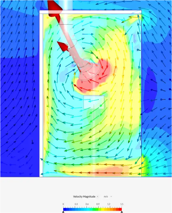
Dust collection and ventilation systems are designed around airflow, but airflow inside a working facility is rarely simple. Production equipment, heat sources, building geometry, makeup air, exhaust systems, open doors and even seasonal conditions can all influence how air moves and where dust and fumes travel.
In a straightforward application, established engineering calculations may provide everything needed to design an effective system. But in larger or more complex environments, multiple factors may interact in ways that are difficult to visualize or predict from calculations alone.
Computer-based modeling can help engineers answer questions such as:
- Where are dust or fumes likely to travel after they leave the source?
- How will supply and exhaust air interact across the facility?
- Are cross-drafts interfering with source capture?
- Where should filtration or ventilation equipment be located for the greatest effect?
- How might changes in airflow, equipment placement or system configuration affect performance?
- Which design concept is most likely to deliver the desired result before equipment is installed?
By making these interactions visible, modeling gives engineers another layer of information for evaluating complex dust, fume and ventilation challenges.
Types of Computer Modeling Used in Dust Collection and Ventilation
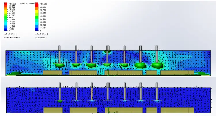
Computer-based modeling can take several forms depending on the questions engineers need to answer. Not every project requires CFD analysis; often, different modeling tools are used together to build a more complete picture of the facility and proposed system.
3D Facility and System Modeling
Three-dimensional models can recreate the facility layout, production equipment, structural features, ductwork and proposed dust collection or ventilation equipment. These models help engineers evaluate equipment placement, identify physical constraints, plan duct routing and coordinate a system with the surrounding process and building.
Airflow and System Modeling
Engineering software can be used to model airflow through ductwork and ventilation systems, including air volumes, velocities, pressure losses and system resistance. This helps engineers evaluate system performance, balance airflow requirements and understand how changes in one part of the system may affect another.
Computational Fluid Dynamics (CFD)
CFD modeling provides a more detailed simulation of how air moves through a facility or around a process. Engineers can use CFD airflow analysis to visualize air velocity, direction, pressure and circulation patterns and to evaluate how changes in equipment placement, supply air or exhaust configurations may influence performance.
Dust, Fume and Contaminant Dispersion Modeling
For some applications, CFD models can also incorporate the movement of dust, fumes or other airborne contaminants. This can help engineers evaluate where contaminants are likely to travel, how effectively they are captured and how different ventilation strategies may affect concentrations throughout the modeled space.
What CFD Modeling Can Tell Engineers
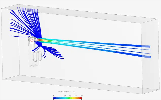
CFD modeling for dust collection and industrial ventilation gives engineers a way to test how air and contaminants may behave under different conditions before changes are made in the facility. Instead of relying only on calculations or assumptions, engineers can visualize complex airflow patterns and compare potential solutions in a virtual environment.
Depending on the application, CFD airflow analysis can help engineers:
- Visualize airflow patterns to see how air moves through and around equipment, structures and work areas
- Track dust and fume movement to better understand where contaminants may travel after they leave the source
- Evaluate source capture performance and identify cross-drafts or other airflow conditions that may interfere with effective capture
- Optimize equipment placement for ambient filtration, supply air, exhaust or other ventilation components
- Compare design alternatives by modeling different airflow rates, equipment locations or ventilation strategies before implementation
- Identify unintended interactions between process exhaust, makeup air, HVAC systems and other sources of airflow
- Refine complex system designs where facility geometry, multiple contaminant sources or changing operating conditions make performance difficult to predict
The goal is not simply to create a sophisticated simulation. It is to give engineers better information for making practical design decisions, reducing uncertainty and improving the likelihood that the finished dust collection or ventilation system will perform as intended.
Advanced Modeling. Experienced Engineering.
RoboVent uses some of the most advanced computer modeling and CFD software available today to analyze airflow, contaminant movement and system performance in complex industrial environments.
But powerful software is only part of the equation. The value comes from pairing advanced modeling tools with experienced engineers who understand dust collection, industrial ventilation and real-world manufacturing processes. RoboVent’s engineering team brings decades of experience solving challenging applications, from heavy weld fume and difficult source capture to complex bulk and powder processes.
That combination of advanced technology and practical engineering expertise helps RoboVent move beyond simulation to develop solutions that can be built, installed and validated in the real world.
CFD and computer modeling are just one part of the broader VentMapping® engineering toolbox. Depending on the challenge, RoboVent may combine modeling with onsite evaluation, facility testing, airflow measurements, engineering calculations and system design to arrive at the right solution.
Have a complex dust, fume or ventilation challenge?
Talk to RoboVent about how advanced modeling and VentMapping® can help you see the problem more clearly and engineer a better solution.


